|
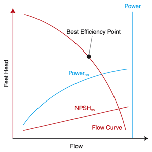
Masterflex makes every attempt to publish a representative flow versus back pressure curve. In many cases, we can also furnish performance curves that quantify parameters such as NPSHreq. NPSHreq: The Net Positive Suction Head that must be available to the pump for cavitation-free operation. NPSHreq is typically expressed in either foot of head or units of pressure. Head, also called discharge head or discharge pressure, is the total pressure force pushing back on the outlet of the pump. Head can usually be calculated by measuring the static height of the liquid plus the friction loss for the piping. If there are other restrictions in the line, such as a bend or narrowing flow restriction, this will increase this value as well. Suction and pressure Suction or suction head is the force on the inlet that the pump needs to pull against. If the height of an open tank of fluid is below the pump inlet, this will typically be a negative pressure (or vacuum) the pump must overcome. If the tank is above the level of the pump inlet this is called flooded suction and is a positive pressure value, which can help push the liquid through the pump. There isn't a formula for PSI: Pressure is a scalar quantity, or a measured force, and PSI is a unit of pressure expressed in pounds of force per square inch of area. 14.7 PSI = 1 bar = 100 Kilopascals. Pressure is typically expressed as a gauge pressure, which is the pressure difference from the local atmosphere. Compared to a perfect vacuum, the atmospheric pressure at sea level is typically 14.7 PSI or 1 bar. Total dynamic head is the pressure for the full system, taking account of both the discharge head pressure and the suction head pressure to show the overall work the pump must overcome. The best efficiency point is the point at which effects of head (pressure) and flow converge to produce the greatest amount of output for the least amount of energy.
- NPSHavail = ha - hvpa - hst - hfs when suction lifts fluid
- NPSHavail = ha - hvpa hst - hfs for flooded suction
- ha = absolute pressure (in feet of the liquid being pumped) on the surface of the liquid supply level (this will be barometric pressure if suction is from an open tank or sump; or the absolute pressure existing in a closed tank such as a condenser hotwell or deareator).
- hvpa = The head in feet corresponding to the vapor pressure of the liquid at the temperature being pumped.
- hst = Static height in feet that the liquid supply level is above or below the pump centerline or impeller eye.
- hfs = All suction line losses (in feet) including entrance losses and friction losses through pipe, valves, and fittings.
Friction losses in pipes is commonly calculated with the Darcy-Weisbach equation, in which:
hf = f x
L
x
V
2
D 2g
- hf = friction loss in feet of liquid
- f = friction factora dimensionless number which has been determined experimentally and for turbulent flow depends on the roughness of the pipe's interior surface and the Reynolds number.
- L = pipe length in feet
- D = average inside diameter of pipe in feet
- V = average pipe velocity in ft/sec
- g = gravitational constant (32.174 ft/sec2)
The Reynolds number is determined by an equation in which:
R =
VD
n
- D = inside diameter of pipe in feet
- V = average pipe velocity in ft/sec
- n = kinematic viscosity in ft2/sec
In the case of a viscous (laminar) flow, in which the Reynolds number is below 2000, the friction factor is determined by the following equation in which:
f =
64
R
- In the case of turbulent flow, in which the Reynolds number is above 4000, the friction factor can be determined by the following equation developed by C. F. Colebrook:
ρ = [-2 log10 (
Ε
2.51
)] -z
3.7D R√f
- ρ = density at temperature and pressure at which liquid is flowing in lb/ft2
- Ε = absolute roughness (see Pipe Absolute Roughness table below)
- D = inside diameter of pipe in feet
- R = Reynolds number
- f = friction factor
- z = absolute or dynamic viscosity in centerpoises
- please see original article for correct formula structure [LS1]
| Type of pipe |
Absolute Roughness (Ε) in feet |
| Drawn tubing (glass, brass, plastic) |
0.000005 |
| Commercial steel or wrought iron |
0.00015 |
| Cast iron (asphalt dipped) |
0.0004 |
| Galvanized iron |
0.0005 |
| Cast iron (uncoated) |
0.00085 |
| Wood stave |
0.0006 to 0.0003 |
| Concrete |
0.001 to 0.01 |
| Riveted steel |
0.003 to 0.03 |
Importance of knowing how to read a pump curve Knowing how to read a pump performance curve properly is key for any lab worker. With this information in your back pocket you can determine the right equipment for your needs. For more information on our products or how to read a pump curve, contact us today. We’re here today to make tomorrow easier.
|