| When a flow meter application involves the use of high viscosity liquid, the end-user must be very careful in choosing an appropriate meter. Using a flow meter calibrated for water can cause very large errors when that same flow meter is used for higher viscosity liquids. The first half of this article will define some of the basic terms relating to viscosity, viscous fluids and the reason why viscous liquids can cause large errors in flow measurement. The second half will discuss the oval gear technology as applied to viscous fluids and provide successful application examples and some common fluids that have been used with oval gear flow meters. For purposes of this article, the terms "liquid" and "fluid" will be used interchangeably. Definition of Viscosity First, let's define viscosity (more correctly, absolute or dynamic viscosity) first in a rigorous manner and then in a more intuitive style. Viscosity (n) is defined as the ratio of shear stress (t) to shear rate (y) (Figure 1). If we were able to isolate a cubic volume of fluid (right), we could visually see the shear stress as the relative force (F) between the upper and lower faces of the cube per unit area (A). The rate of shear is then defined as the relative velocity (V) between the upper and lower faces divided by the length between them (L). The units of shear stress are given as dynes per square centimeter. For shear rate, the units are s-1. This gives the viscosity in (dyne sec)/cm2 or centipoise. An over-simplified but more intuitive grasp of viscosity can simply be stated as the measure of internal friction that arises whenever a liquid flows. Essentially, the stickier the liquid and the more it resists the tendency to flow, the higher its viscosity. 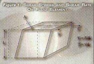
Kinematic vs Dynamic Viscosity Another concept to understand is the relationship between dynamic viscosity (as given in the above definition) and kinematic viscosity. Kinematic viscosity is defined as the dynamic viscosity divided by the density of the fluid. Because density is an intrinsic property in itself, it can be argued that kinematic viscosity is not a precise measure of internal fluid friction. However, kinematic viscosity is the preferred unit when the shear stress and shear rate of the fluid is influenced by the density. An example of this is the measurement of viscosity using gravity techniques such as a cup with a small orifice in the bottom. With this type of measurement device, a specific volume of fluid passes through the orifice and the time it takes for the volume of fluid to pass through the orifice is proportional to the fluid viscosity. However, it also depends on the density of the fluid since the more denser the fluid, the faster it will flow through the orifice. The property being measured in this example is then the kinematic viscosity and not the dynamic viscosity. Kinematic viscosity is given in units of centistokes while the dynamic viscosity is given in centipoise and the conversion from dynamic to kinematic is given by dividing the dynamic viscosity by the fluid density in g/cm3. Since some manufacturers spec out viscosity in centipoise and others in centistokes, it is somewhat important to know the difference between the two and to be able to convert from one to the other. Newtonian vs Non-Newtonian Fluids A Newtonian fluid is one in which the viscosity does not depend on the shear rate no matter what shear is applied, the viscosity stays the same. In many applications, however, this is not the case and, as the fluid is sheared at greater rates, the viscosity will change. These types of liquids are known as non-Newtonian and there are many classifications (Figure 2). 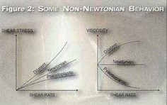
A dilatant fluid will increase its viscosity with increasing shear rate (such as a cornstarch/water mixture) while a pseudoplastic fluid will decrease its viscosity with increasing shear rate (such as most paints). Another classification of non-Newtonian liquids is what is called a plastic fluid. A plastic fluid will behave as a solid until a critical shear rate is reached (called the yield value). At the yield value, the fluid will start to flow and as the shear rate continues to increase, the fluid may then exhibit Newtonian, dilatant or pseudoplastic characteristics. As everyone will attest, ketchup is a good example of a plastic fluid as it is difficult to pour unless the appropriate rate of shear is applied—in this case, a simple shaking of the bottle. Two additional classes of non-Newtonian which deserve mention (Figure 3). The first is called thixotropic and occurs when a fluid experiences a decrease in viscosity over time while the rate of shear is constant. The other type of fluid, known as rheopectic is just the opposite. It exhibits an increase of viscosity over time as the shear remains constant. Obviously, it is very important to fully identify the characteristics of the fluid. Trying to pump a dilatant fluid could have disastrous consequences to the application. 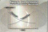
Temperature Effects Typically, viscosity is inversely related to temperature with some fluids showing as much as a 10- to 12-percent change in viscosity per degree Celsius. If the fluid temperature is expected to change, it should be understood what effect this will have on the fluid viscosity and the application. Viscosity-compensated flowmeters are insensitive to a wide variety of viscosities (and densities) but they do have limits. Make sure to plan for worst case conditions and follow the manufacturer's guidelines and specifications when selecting a flowmeter technology. What's the Problem with Viscosity? Why does viscosity pose a problem in flowmeter applications? To answer this, let's consider a direct-reading variable area flowmeter that is calibrated for water. With the variable area design, the float moves up a vertical tube as the flow rate increases. At constant flow, the float is in equilibrium between the upward force of the fluid and the downward force of gravity. Imagine the water rushing past the float (Figure 4). 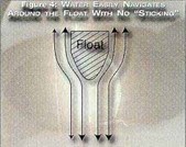
The water easily moves around the cross-sectional perimeter of the float with virtually no fluid sticking to the float. As the fluid viscosity increases however, fluid starts sticking to the float, building layer upon layer of fluid drag zones, each with a different relative velocity (Figure 5). This effect will cause a slow-moving viscous liquid to yield the same buoyant force as a fast moving low viscosity liquid. This effect can be quite large, as one U.S. food processor found out. This particular company wanted to measure the flow of canned milk in their lines. Even though the viscosity was only 15 centipoises, the variable area flowmeter, which was calibrated for water, read two times too high. At higher viscosities, this effect is even more pronounced. Another manufacturer of metal stamping equipment was using a variable area meter to read a water-soluble oil/water mixture at 60 centipoise. In this example, the customer's meter read six times too high. In order to make a flowmeter insensitive to viscosity, the key is to use a flow technology that relies on some static property of the fluid, like conductivity, incompressibility or heat capacity. One technology, the oval gear flowmeter, uses the property of incompressibility. While all fluids can be compressed to some extent, the effects are so negligible as to not affect the intrinsic accuracy of the oval gear flowmeter. 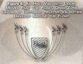
The Oval Gear Flow Meter The design of the oval gear flow meter is relatively simple; oval shaped gear-toothed rotors rotate within a chamber of specified geometry. As these rotors turn, they sweep out and trap a very precise volume of fluid between the outer oval shape of the gears and the inner chamber walls with none of the fluid actually passing through the gear teeth (Figure 6). Normally, magnets are embedded in the rotors which then can actuate a reed switch or provide a pulse output via a Hall Effect sensor. Each pulse or switch closure then represents a precise increment of liquid volume that passes through the meter. The result is a high degree of accuracy (.5 percent of reading) and resolution and almost negligible effects for varying fluid viscosity, density and temperature. 

The accuracy of the oval gear flowmeter depends on the viscosity and the higher the viscosity, the better the accuracy. The reason for this has to do with fluid slippage between the gears and chamber walls. Fluid slippage will cause a slight degradation in accuracy with low viscosity fluids being more prone. As the viscosity increases, the wall slippage quickly becomes minimal and the best accuracy is realized. Even with water-like fluids, the accuracy is generally very good, but check with the manufacture if there is a concern. Most manufacturers should be able to give you accuracy ratings for both water-like liquids and higher viscosity fluids (usually above 5 or 10 cp). Installation of oval gear meters is simple since most designs allow for either horizontal or vertical mounting. Because no straight pipe runs or flow condition is required, the meters can be installed in tight areas, allowing for more flexibility in application design. The oval gear design works best when there is a little back pressure in the line, a throttling valve on the meter outlet usually works just fine. Regarding process connections, NPT threads are popular but many manufacturers offer ANSI flange connections for larger pipe sizes and specialized connections such as 3A Tri-Clover fittings for sanitary applications. When sizing an oval gear flowmeter to your application, keep in mind that the higher the viscosity of your fluid, the more pressure will be required in order to "push" the fluid into the flowmeter and around the gears. Essentially, the pressure drop is the only limiting factor when the application requires the metering of extremely high viscosity liquids. For example, it will require much more pressure to push through molasses than glycerine. The general rule is as long as the fluid will flow and as long as there is enough pressure, the oval gear meter will be able to measure the flow. In applications where the lowest possible pressure drop is required, some manufacturers can substitute specially cut high viscosity rotors for the standard rotors. The manufacturer will be able to provide you with a graph of flow rate versus pressure drop for various viscosities. Summary Although this article has focused on viscosity, it is important to note that other parameters will affect the flow meter choice in an application. Viscosity, density, pressure and fluid purity must also be considered, as well as other factors such as vibration, rangeability and required response time. The oval gear flowmeter, although representing a popular choice, is just one design out of many positive displacement technologies that can handle high viscosity flows. Because of its relatively low cost, forgiveness of fluid density and viscosity, and ease of installation, the oval gear flowmeter is appropriate for consideration when reviewing your application needs. Appendix A Fluid Examples Suitable for Oval Gear Flow Meters Although not exhaustive, the following list represents the range of fluids that can be used with the oval gear flowmeter.
- Measurements of sugar solutions, syrups, oils, sauces, beverages, honey, molasses, milk products, juices, chocolate and coatings in the food industry.
- Alcohols, syrups, glycerines and coatings in the pharmaceutical industry
- Shampoos, gels, perfumes and creams in the cosmetics industry
- Fuels, lubricants and petro derivatives in the oil and gas industries
- Chemicals, fluoride and acids in the water and wastewater industry
- Wax finishes, perfumes, dyes and acids in the pulp and paper industries
- Solvents and inks in the printing industry
- Transmission fluid and hydraulic oil in the automotive industry
- Dyes, bleach and chemicals in the textile industry
- Oils, gasoline and kerosene in the petroleum industry
- Solvent and latex based paints
Appendix B Oval Gear Flow Meter Application Examples by Industry Chemical Oval gear meters have been successfully used for measuring flow rate and flow total (volume) of chemicals in batching applications. Using a batch controller along with an oval gear flowmeter, preset volumes of chemicals can be automatically dispensed. Measurement information can be sent to a computer or PLC for datalogging. Energy Another application of the oval gear flowmeter is the measurement of net fuel usage in boilers and engines. By placing one oval gear meter in the supply line and one on the return line, the total net fuel usage is determined. Hydraulic In bearing lubrication, the oval gear flowmeter can be used to insure sufficient delivery of lubricant and, through the use of a controller, provide a means of automatically shutting down the machinery in case of low flow or no flow conditions. Pulp and Paper Oval gear meters can be used with paper finishing chemicals to insure proper rate of delivery and to keep track of the volumes dispensed. The monitoring of wax finishes, perfumes and sizing chemicals that are sprayed onto the paper are all viable applications. Food and Beverage Oval gear meters have advantages in the food and beverage industry. They are used to monitor syrup injections in main beverage lines, monitor and batch volumes of candy coatings, and the accurate and automated dispensing of cooking oils. For food and beverage applications, 3A sanitary fittings are offered by some manufacturers.
|